

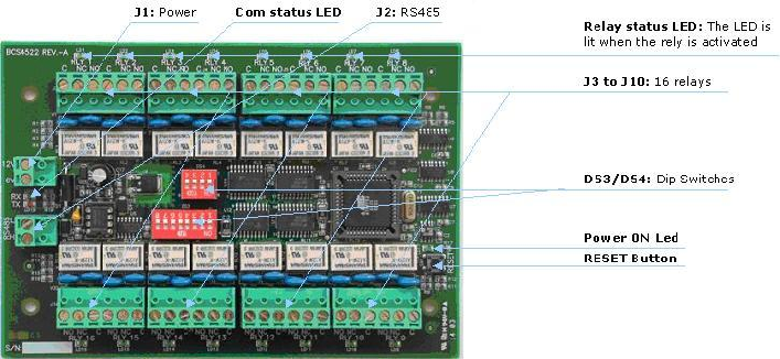
Board description
Preface
The SAT16 is a board with 16 relays. It is a slave board to a master controller.
Currently there are two types of Sensor controllers that can act as masters for the SAT16: IC2001/4001 and IC1604
Though the future it would be possible to connect the SAT16 directly to the PC, but at this point it can only receive commands from a master controller and therefore it must be connected to the 2nd RS485 communication port of either the IC2001/4001 or the IC1604.
To each master it is possible to connect up to 3 SAT16's.
Therefore, together with the optional on-board extension relay board, the RLY-12, you can get a 64 relays controller. As follows:
Main controller (IC2001/4001 or IC1604): Relays 1 to 4
RLY-12: Relays 5 to 16
SAT16 #0: Relays 17 to 32
SAT16 #1: Relays 33 to 48
SAT16 #2: Relays 49 to 64
Note that when using the SAT16 , the 2nd communication port of the controller must be dedicated for the SAT16 and cannot be used for other tasks such as alarm priority bus, network reflexes, etc.
SAT16 Addressing
The 5 switches jumpers DS3/7, DS3/6, DS3/5, DS3/4, DS3/3 should be set the same as the master controller address.
Note: DS3/3 matches the LSB of the master controller.
For example: say the master controller address is 18 (i.e., 10010),
thus the corresponding five SAT16 switches (DS3/7 to DS3/3) should be set as follows: DS3/7 = ON; DS3/6 = OFF; DS3/5 = OFF; DS3/4 = ON; DS3/3 = OFF;
The 2 switches DS3/2, DS3/1 should be set to 00, 01 or 10 according to the address of that SAT16 from 0 to 2 in case there are more than one SAT16 units connected to the same controller. I.e.,:
The 1st SAT16 of a controller (relays 17-32) should have DS3/2 = OFF; DS3/1 = OFF;
The 2nd SAT16 of a controller (relays 33-48) should have DS3/2 = OFF; DS3/1 = ON;
The 3rd SAT16 of a controller (relays 49-64) should have DS3/2 = ON; DS3/1 = OFF;
See the following table:
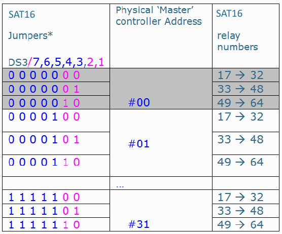
*‘0’ means jumper ‘off’, ‘1’ means jumper ‘on’.
Notes:
- In case the SAT16 is already in power, any change in the address settings must be followed by a power reset to the SAT16.
- The DS4 dip switch is not used.
Assembly instructions
Connect the RS485 connector with the 2nd communication port of a IC1604 or TPL Rev.D1 or higher controller equipped with the "Kit Com2".
(Kit Com2 are the 2 ICs near the 2nd port. On the IC2001/4001 these are U29 & U30, and on the IC1604 – U16 & U17)
Connect the J1 connector with the 12VDC / 250mA Power supply.
SAT16 Baud rate
The default baud rate of the SAT16 satellites is 4800.
When a SAT16 is connected to the controller, it automatically adjusts its baud rate to that of the controller.
Comments
0 comments
Please sign in to leave a comment.