

Fitting Instructions for ML0100 - Z & L Bracket set for Slimline Magnets
The ML0100 Z&L Bracket set is designed for Inward opening doors and is used with the Slimline Range of Magnetic locks: ML0080 & ML0074.
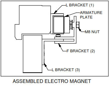
There are 3 Brackets supplied:
- 'L' Bracket which allows the Magnetic lock to be fixed to the Header Frame.
- 'F' Bracket which holds the Armature plate.
- 'L' Bracket with 5 Counter sunk holes and 2 Slotted
holes which fits into the channel on the 'F' Bracket and fixes to the door face. (Brackets 2 & 3 become the 'Z'
bracket).
Installation to an Inward Open door using 'Z & L' Bracket set - Steps 1 - 5
- Check that the Magnet and Brackets will fit to the Door and
Head Frame
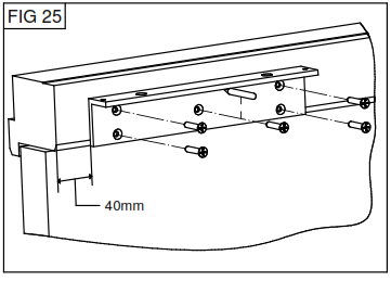
- With the door closed and latched use the 'L' bracket No 1 as a template.
Place the left side of the 'L' bracket 40mm from the top corner of the door and ensure the bottom of the bracket is level with the bottom of the head frame. (see Fig.25).
- Mark the centre of each fixing hole on the 'L' bracket and Drill holes 3.5mm Dia x 25mm depth. The 'L' bracket must be fitted flat against the head frame.
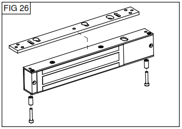
- Using the Allen key wrench remove the two M4 Allen screws and metal spacer through the bottom of the magentic lock.
Lift up the mounting plate and remove it from the magnet (fig 26).
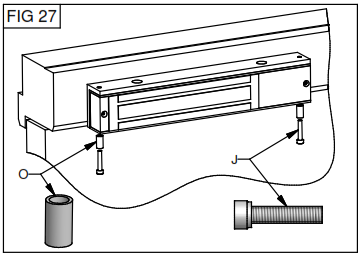
- Fix the magnet to the 'L' bracket using two M4 Allen bolts and metal spacer fixed through the holes in the bottom of the magnet and tighten with the Allen key wrench (see Fig.27).
Installation to an Inward Open door using 'Z&L' bracket set - Steps 6 - 19
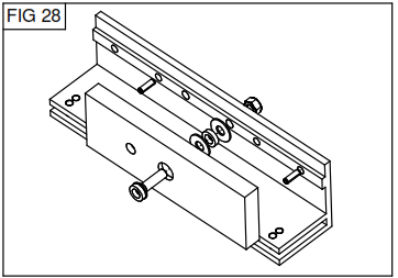
6.Gently tap the 2 guide pins into the holes on the back of the Armature plate.
Push the M8 35mm Allen bolt through the counter sunk hole in the Armature plate followed by one rubber washer sandwiched between 2 Steel washers behind the Armature plate. (fig.28).
- Fix the Armature plate to the 'F' bracket (No 2) through M8 tapped hole on the right and tighten with the 5mm Allen key wrench, allow a gap of 3-5mm behind the Armature plate.Fix M8 nylock nut at the back of the bracket (see Fig.28)Do not apply thread lock at this stage.
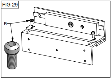
- Slide the 'L' bracket No.3 (Slotted holes side) into the channel of the 'F' bracket so that the 2 brackets form a 'Z'shape (see Fig.29).
- Loosely fix together the 2 brackets using the 2 M6 Allen bolts through the first holes on the 'F' bracket (see Fig.29).
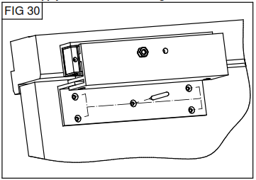
- With the door closed and latched place the 'Z' bracket over the magnet so that the Armature plate covers all three silver bars and hold in position (see Fig.30).
- Push the bottom section of the 'Z' bracket forward until it touches the door face. Mark the centre of the 5 countersunk holes (see Fig.30)
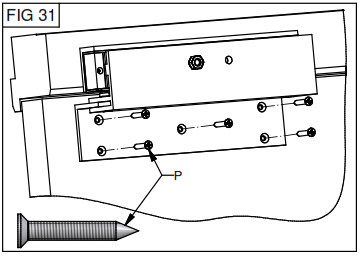
- Drill 3.5mm Dia holes to a depth of 25mm and fix 'Z' bracket to the door using 5 No.10 32mm screws.
- Adjust the top bracket towards the door so that the Armature plate is touching the magnet face.
Carefully open the door and tighten the 2 M6 Allen bolts. (see Fig.31).
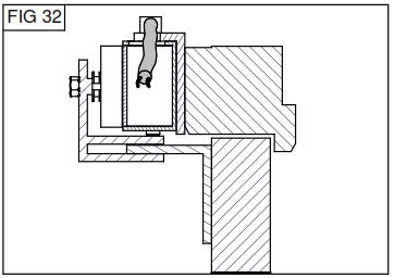
- Pass lock cable through the 10mm hole in the 'L' bracket (fig 32) and connect to Magnet PCB as per wiring instructions on pages 7&8 of the Magnet instructions.
- Apply voltage to the Magnet. Close the door and check Armature plate is correctly aligned with the magnet.
Apply firm pressure against the door to check magnet is holding properly.
Remove voltage and open the door.
- Remove M8 Allen bolt from Armature plate and apply Thread lock.Re-fit as per step 6&7.
- Remove one at a time the M4 Allen bolts from the bottom of the magnet and apply Thread lock. Re-fit as per step 5.
- Remove the M6 Allen bolts (R) from the 'Z' bracket and apply Thread lock. Refit as per Step 13.
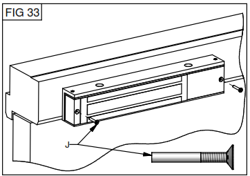
- Using the two M3 18mm Csk screw fix the PCB cover plate in position on the magnet and into the counter sunk hole at the opposite end (see Fig.33).
These screws will prevent the M4 Allen bolts from unscrewing.
Installation to Pair of Inward Open doors using two 'Z & L' Bracket sets
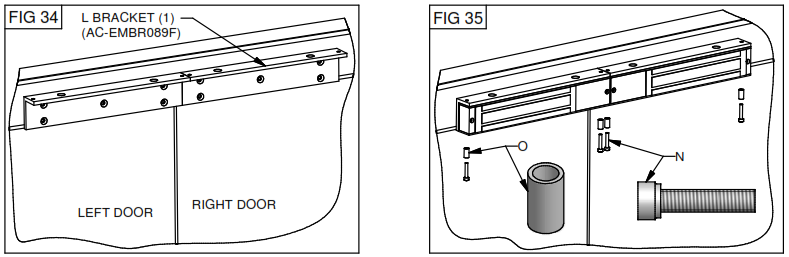
- With both doors closed and latched use the two 'L' bracket No.1 as templates and place together on the frame (see Fig. 34) ensure the bottom of the brackets is level with the bottom of the head frame. Mark the centre of the counter sunk holes on each bracket and drill holes 3.5mm Dia x 25mm depth. Fix using ten No.10 x 32mm Csk screws.
- Remove the four M4 allen bolts and Metal spacers as per step 5 page 1 of bracket instructions (see Fig.26).
- Fix the Magnet to the two 'L' brackets using four M4 Allen bolts and Metal Spacers (see Fig 35).
- Assemble the Armature plate and 'Z' bracket as per steps 6 - 9 (Fig.28&29).
- Adjust and fix each 'Z' bracket as per steps 10-13 (Fig.30&31)
- Fit 2 seperate cables for each magnet PCB as per steps 14&15 (Fig.32)
- Apply Thread lock to Allen Bolts as per steps 16 - 18.
- Fit four M3 18mm Csk screws as per step 19 (Fig.33).
Comments
0 comments
Please sign in to leave a comment.