

This article deals with issues relating to failing communication between the GuardPointPro server and a controller.
Please follow these points to fix possible bad communication issues, covering all controllers.
Diagnosis:
A controller which was communicating perfectly does not communicate with the software for a long period of time, i.e. on the Real time event window there are messages like "some commands returned error 263 Timeout”, or no events are displayed.
Pressing on the Reset button of the controller does not give any event on the software log screen but doors are still opening with codes and tags means that the controller is still working in stand alone mode.
The controller does not communicate at all:
Solutions:
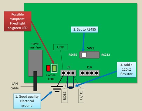
If the Green communication LED is constantly ON:
→ Disconnect the controller from its communication bus.
If the LED is still ON, remove the communication component (the one marked ‘Max3085’).
If the LED switches OFF, replace the component as it is faulty.
Do not change the component on a powered controller.
→ Check Rx and Tx (or Hi and Lo) communication wires were not cut.
→ If using a switch mode PSU please ensure you have installed the 120Ω resistor.
For a single controller:

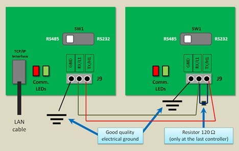
For 2 or more controllers sharing the same RS485 bus, the 120Ω resistor should be installed ONLY on the last controller:

If the VCC/RST LED blinks:
- Power off the controller
- Remove the ROM
- If there are Kit Com2 components remove them
- Power up and try to read the Boot version with the Flash2000 software.
If the VCC/RST Led doesn't blink after 2-3 minutes, insert the ROM and try to read the boot again.
If the communication is OK, flash the controller with its specific firmware and initialise in GPP.
If the Led still blinks after 2-3 minutes, please contact Sensor for ROM replacement.
If the Led still blinks after 2-3 minutes, try to clear the RAM:
- Power off the controller
- Remove the Lithium jumper (JP1)
- On the ROM, shortcut pin 5 with pin 8 together for 5 seconds

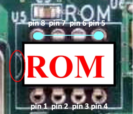
- Set the JP1 back with the power
- Check if the communication is restored
- If not, the controller is faulty - please contact support@sensoraccess.co.uk
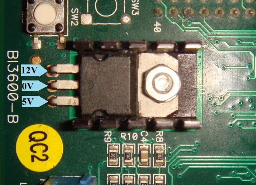
If the controller communicates via TCP module:
→ When the board is powered and connected to the 100Mb Ethernet switch.
Measure the voltage at the regulator located on the board and check that the voltages are close to the following. If not, the board is faulty.

Ping the TCP module and check if there is a latency.
If the latency is more than 20ms, open the GPP.ini file and set the option "MotorComNet" = 0.
Restart the GPP server and check again.
The option "MotorComNet = 1" means GPP uses the newer VB.NET communication layer. This should work better with larger networks.
The option "MotorComNet = 0" allows GPP to use the older communication layer.
We discovered that the new VB.NET communication motor is not handling the latency issues very well whereas the old COMs layer is able to deal with high latency better.
→ Create a virtual Com port with VSP Manager this application is located in the Tibbo Toolkit download the 32 bit from here, download the 64 bit from here
Try to communicate via this Com port. If comms is succesfull, either the "UDP_Conf.exe" file is not located in the GPP folder (see the previous point) or the machine has some issue with its network board. In the last case, try a reboot of the server
→ It is possible that the TCP converter (Tibbo or Lantronix module) is working at a different baudrate than the controller baudrate (eg. GPP baudrate is at 19200, Tibbo is at 38400 and controller is at 9600).
Try to change the baudrate of the TCP converter (eg. 9600) via its configuration tool (DS Manager or Device Installer) and then try to communicate with DBCOM with this controller.
→ Check if the "UDP_Conf.exe" file is located in the GPP folder. If not your antivirus has probably deleted it.
To solve this issue, re-install GuardPoint Pro and configure it as a safe file in anti-virus settings.
→ Create a virtual Com port with VSP Manager (this application is located in the Tibbo Toolkit) and try to communicate via this Com port.
If it works, either the "UDP_Conf.exe" file is not located in the GPP folder (see the previous point) or the machine has some issue with its network board. In the last case, try to reboot the machine.
If none of the previous cases has solved your issue:
→ Open the Windows Task Manager on the GPP server and check that there is only one GPP process that is running. If not, close GPP and close all the GPP processes and restart the GPP software.
→ As controllers cannot communicate with more than one GPP server at the same time, make sure that GPP server is not running on another machine.
→ Try with Flash 2000 to read the BOOT* version. If you cannot read it remove the ROM component. If the ROM still cannot be read try to replace the communication component (the one marked ‘Max3085’). Do not change the component on powered controller.
→ Try with Flash 2000 to read the Firmware version. If you get something like AB/CD/EF, download the firmware and try again. If you still do not get the firmware version, try to replace the ROM component. Do not change the component on powered controller.
In case the controller communicates sometimes:
Solutions:
If the Green communication LED is constantly ON:
→ If using controllers with Switch mode PSU ensure the 120Ω resister is installed at the end of line for each network
If the Reset LED blinks sometimes:
- Power off the controller
- Remove the ROM
- If there are Kit Com2 components remove them
- Power up and try to read the Boot version with the Flash2000 software.
If the LED does not blink after 2-3 minutes, insert the ROM and try to read the Boot again. If the communication is OK, flash the controller and initialize it with the software. If the Led still blinks after 2-3 minutes, replace the ROM.
If the Led still blinks after 2-3 minutes, try to clear the RAM:
- Power off the controller
- Remove the Lithium jumper (JP1)
On the ROM, shortcut pin 5 with pin 8 together during 5 seconds


- Set the JP1 back with the Power
- Check if the communication is restored
If not, the controller is faulty. Contact support@sensoraccess.co.uk
→ Check the temperature of the controller room.
We have noticed that when the controllers are located in an environment of high temperature (80 deg. C) the Tibbo module would no longer respond. In this case, reset the controller to regain communication.
→ If using SQL databases on Windows Server 2003 SP2, Microsoft has published that a Windows component on Windows Server 2003 SP2 causes issues on SQL Server systems such as general network errors and working set trimming. The Microsoft correction should be installed.
The correction is available here: http://support.microsoft.com/kb/948496
For more details, look here: http://blogs.msdn.com/b/psssql/archive/2008/10/01/windows-scalable-networking-pack-possible-performance-and-concurrency-impacts-to-sql-server-workloads.aspx
→ TCP module of Tibbo are very sensitive to broadcasting. If there are cameras or other devices in the same network, that could cause communication interferences with the Tibbo boards.
In such case, the controllers network should be installed in a separated network like VLAN/VPN.
→ If using a TCP module of Tibbo and the red Tibbo led is blinking.
This means that the Tibbo module has entered into its programmation mode.
In this case, setting the INI option ResetTibbo=1 and restarting GPP could help.
If none of the previous cases has solved your issue:
→ Open the Windows Task Manager on the GPP server and check that there is only one GPP process that is running. If not, close GPP and close all the processes and restart the GPP software.
→ Try to increase the controller baudrate (i.e. to 38400) when the communication is retrieved and then check if it improves the communication.
→ Check that the controller network defined in the corresponding screen of the software has polling settings reasonable for the installation. For example, if the network has a latency and the polling timeout is 50msec, there will be communication errors non-stop. You are invited to contact us to get tips on our recommendations.
→ Check that the RS485 bus is not cabled as star configuration.
→ EMI can affect the bus. Check the RS485 bus. If the bus length is more than 500m, install 120 ohms resistors at each end of the bus. The maximum distance between controllers and RS485 bus is 3 meters. The bus cables must be twisted and shielded. Link all the RS485 wire shields together and connect them at the RS232/RS485 interface end and NOT at the controllers end. RS232/RS485 interface must be connected to a reliable ground. Cut the welded wire ends and strip the new ends. Check that the screws/nuts are securely fastened. Use a line protection (like SP200) if necessary.
→ Faulty controllers can affect communication across the network. In this case, find the faulty controller by disconnecting all the controllers and then progressively connecting back the controllers, one after the other, until the problem appears: the last controller connected is the faulty one. Then unplug all connectors from this controller (door openers, readers, etc..), then reconnect them gradually in order to find the source of disturbance (wire terminations not isolated, two wires in contact, etc.)
In case the controller has pending commands:
Display the commands for information (in the Tool>Options>Journal GPP screen) and look at the grey commands:
If receiving 'Error 263'. Timeout:
→ Try to increase the controller baudrate (i.e. to 38400) when the communication is retrieved and then check if it improves the communication.
→ Open the Windows Task Manager on the GPP server and check that there is only one GPP process that is running. If not, close GPP and close all the processes and restart the GPP software.
→ Ensure there is no other GPP server that is communicating with the same controller network.
Comments
0 comments
Please sign in to leave a comment.