

1. Wiegand technology
Sensor controllers may read up to 66 bits Wiegand string, via the inputs data.
Several pre-defined formats are recognised by the controllers and the 66 bits read, according to the format selected,may contain card code, site code and parity bits.
See Table 1.1 below for the formats description.
The format recognised at a reader is programmed from the PC application via Mess 03. From the GuardPointPro application, it is defined through the ‘Controller/Reader/Miscellaneous-Badge format’ screen. In addition, other formats may be programmed by users.
Note: each reader may have a different format
1.1 Pre-defined formats
Table 1.1 shows the pre-defined format recognised by the controllers. Each Wiegand string may include up to 66 bits represented as follows:
b65………b0 (b being the less significant bit)
For each format, the card code and the possible site code are indicated with their bit position in the Wiegand string.
- When jumpers JP4/6,7,8 (or DS1/6,7,8) are in position on,off,off, the controller checks that the card is read correctly i.e. that the number of bits received and the parity bits corresponds to the format defined at the reader. (See table 1.1)
- When jumpers JP4/6,7,8 (or DS1/6,7,8) are in position off,on,off, the controllers doesn’t check the card reading. (not recommended)
The pre-defined format is sent to the controller with Mess 03 (see par. 3) where byte 2 is the format number (and bit 7=0)
Multi-format reading:
From version 01/11/09, when different formats are defined for the readers, each reader supports also the 3 other formats defined at the other readers. It’s works as follows:
When a specific format (other than the ‘Hexadecimal’ one) is defined at a reader, if a card passed at this reader doesn’t have the number of bits expected for this format (see table 1.1), the system will check if the number of bits received from the card corresponds to the format defined on one of the 3 other readers. If yes, it will use this format for the card.
If no, the card will not be read except if ALL the readers get the same format. In this case, the card read will be in this format. For example, if the decimal format 01 must be applied to cards with more than 26 bits, the same format 01 must be defined for all the controller readers.
This multi-format is active only if the card verification is set (JP4-DS1/6,7,8=on,off,off). If the card is not checked (JP4/7 or DS1/7 on), the controller will read the card only according to the format defined at the reader used.
Example:
- If formats 1,5,15,17 are defined at the readers 1,2,3 and 4, these 4 formats will be recognised at each reader.
- If format 1 and 17 are defined at reader 1 and 2, and format for readers 3 and 4 are ‘hexadecimal’, format 1 and 17 will be recognised at readers 1 and 2 only.
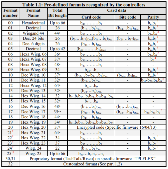
The “Total bit length” column shows how many bits (Data+parity) the Wiegand string may contain.
This information is used for 3 purposes:
Check the card code integrity:
If jumpers JP4/6,7,8 (or DS1/6,7,8) are in position on,off,off, the controller, in addition to the parity bits verification, checks also that it has received the correct number of bits indicated in this column (only for formats for which the total bit length is shown with an asterix).
If these switches are in position off,on,off, the controllers accepts any card code length.
If the total bit length is shown with ‘**’, the controller always checks that it received the correct number of bits (independently of the switches position).
Multi-formats feature (see par. 1.1):
When different formats are used for the 4 readers of a same controller, the controller selects at any reader the format to use according to the number of bits read: the format selected is the one which gets the same “Total bit length” than the number of bits read. This feature cannot be used for formats for which the total bit length is indicated as “up to”.
Biometric readers with error code:
Some biometric readers (fingerprint readers or other) may add a 4 bits error code if the card code has been recognised but the biometric test has failed (wrong finger for example). This total bit length is therefore used by the controller to detect that if it receives the expected total bit length + 4 bits, it means that an error code has be added before the card code.
Notes on card verification:
When jumpers JP4/6,7,8 (or DS1/6,7,8) are in position on,off,off, the controller checks that the card has been correctly read either by checking that the number of bits received corresponds to the number expected (shown on table 1.1) , or by checking the parity bits (see hereunder the parity bits the calculation), or both.
If these switches are in position off,on,off, the controllers doesn’t check the card reading (not recommended).
1: The parity bits are the first (b0) and the last bit (b) received as follows:
- bn is the Even Parity of the half H.S. bits (i.e. bn47 to b if 48 data bits)
- b0 is the odd parity of the half L.S. bits
(i.e. b23 to b024 if 48 data bits)
If odd number of data bits, the middle bit is used for both parity.
For example: for 35 bits of data, E is the even Parity of the fir st 18 bits (b to b17), O is the odd parity of the last 18 bits (b17 to b).
For HID cards, it is recommended to use the Sensor format ‘D10302.CDF’ which is defined as followsL
37 bits as follows : Eb34bbbbbbbbbbbbbbbbb170bbbbbbbbbbbbbbbb0O
Bit E: Even parity for bits bb34 to b17, Bit O: Odd parity for bits b Bits b34b33b32 fixed for all the cards to value 101 Bits b31 to b00 to b0: 8 BCD digits (32 bits) printed out on the card.
2: The 4 parity bits b3b2b1b0 are the XOR of the 10 hexa data digits (40 bit data b)
3: The 4 parity bits b3b2b1b0 are the XOR of the 8 hexa data digits (32 bit data b)
4: The parity bit b0 is the odd parity bit over the 36 bits of data b
5: The 3 bits b31b30b29 = fixed value 101 and the 2 parity bits b136, b as follows:
b1=Even parity of the odd bits (b29,b27,…b1), b0 to b01= Odd parity of the even bits (b)28….b….b28,b26,…b0
6: HID format ‘Corporate 1000-35’: The data bits and the 3 parity bits b34b33 and b0 are computed as follows:
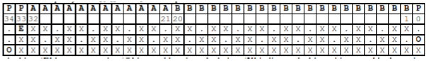
P are 3 parity bits: ‘E’ is an even parity, ‘O’ is an odd parity calculation. ‘X’ indicates the bit positions used in the parity calculation.
AA…A is a 12 bits site (converted in decimal) code and BB..B is a 20 bits card code (converted in decimal).
For this format, if dip switches JP4 or DS1/6,7,8 = off,on,off, the system will not check the parity bits but will check that the card get 35 bits.
To program such a format at reader No.1 using Mess 03 with programmable format (see par. 3), with a site code of 1234, the message to send is: 03 01 81 94 15 8C 00 00 00 00 12 34 00 22 00 00 00 00
- From version 25/11/13
- From version 01/01/14
- From version 03/04/14
Created to bypass a bug on Suprema fingerprint readers (read only 32 or 16 bits and discard an eventual wrong FC code introduced in the Wiegand string)
- From version 12/09/14. Format used for technical support to analyze the whole Wiegand string received by the controller: b39…b0 are the 40 Low Significant Bits received on the Wiegand string and n7..n are the total bit length (the total number of bits received).
To program such a format at reader No.1 using Mess 03 with programmable format (see par. 3), with a site code of 1234, the message to send is: 03 01 81 94 15 8C 00 00 00 00 12 34 00 22 00 00 00 00
- From version 25/11/13
- From version 01/01/14
- From version 03/04/14
Created to bypass a bug on Suprema fingerprint readers (read only 32 or 16 bits and discard an eventual wrong FC code introduced in the Wiegand string)
- From version 12/09/14. Format used for technical support to analyze the whole Wiegand string received by the controller: b39…b0 are the 40 Low Significant Bits received on the Wiegand string and n7..n
are the total bit length (the total number of bits received).
1.2 Format ‘32’: Customized format
Format ‘32’ is dedicated to customised format and depends on the firmware version as follows:
Firmware from 25/11/13:
The card code is the 6 L.S.Digits of the decimal value of bits b
1.3 User defined format (On controllers with firmware version from 2008 only) 31…b0
Mess 03 with bit 7 of byte 2=1 (see Par. 3) allows to define the position of the Card code and the Site code, the size of these codes and if they must be read in hexadecimal or converted in decimal.
If the card verification is set (JP4 or DS1/6,7,8 = on,off,off), the verification is done according to the first and last bits read, which are the parity bits, are described in previous note 1.
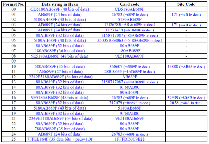
Example : to read a card code of 24 bits from position 01 without site code, use Mess 03 with bytes 2,3,4,5=81,18,00,00. A 32 bits data string (i.e. bits b32….b) 80AB689F will give a card code = AB689F.
If the 24 bits card code from position 01 must be converted in decimal (Mess 03, bytes 2,3,4,5=81,98,00,00), the same 32 bits data string will give a card code = 11233439.
1.4 Serial readers
Sensor Controllers can support serial readers via their serial Port2.
They are programmed as follows:
- On firmware’s 2012: programming is done via the ‘format number’ as follows:
Format No.20: Aperio readers (polling mode); Format No.21: Sensor serial readers (polling mode)
Format No.22: Sensor serial readers (event mode)
On firmwares from 2013, the programming is done via bytes 11,12 of Mess 03 (see par.3 and 4) and any Wiegand format may be used.
2- Magnetic ISO1 / ISO2 (‘Clock and Data’) and Bar Codes Technology
Sensor controllers may read any magnetic card coded into the ISO 1 or 2 standard (track 1 or 2) and any bar code cards in standard 39 and 2/5 interleave. Among all the digits encoded in the card, the controller may identify two codes:
Card Code and the Customer Code
- The Card Code is a code unique to each card. Its place on the data track is user programmable.
- The Customer or Site Code is a code common to all cards pertaining to a same organisation
When defined, controllers will accept only cards with the same Site Code.
This code can have up to 8 digits. Its size, value, and place on the data track are programmable by the user. These user programmable informations are called the system card format which defines the following information:
- The position of the card code (between 00 and 37), the size of the card code (between 04 and 20), the position of the customer code (between 00 and 37), the size of the customer code (between 01 and 08), and the value of the customer code as shown in the example in figure 1:
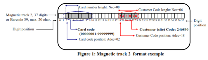
Figure 1: Magnetic track 2 format exemple
This format is user programmable. Therefore, users can use already existing cards by programming the controller with the format of the cards they already use.
Notes:
1- The first digit is in position is '0' (and not '1'), the second digit in position '1' etc.
2- If Customer Code length = 00, the Customer code is not checked.
Comments
0 comments
Please sign in to leave a comment.